Gas Generator

This is not directly related to the Project Earendel, but it is rocket related.  On aRocket, someone had asked for help with a gas generator, specifically asking about the gas to liquid ratio of hydrogen peroxide or a Potassium nitrate  / sugar solid.  Now, I posted a fairly long reply which boils down to you get higher gas to liquid with KNSU, but at the price of higher temperature and lots of liquid or solid K2CO3 (Potassium Carbonate) in the exhaust, so you probably shouldn’t use it. This got me thinking, if I had to run a turbine, quick and cheap for demonstration purposes, how would I go about it?

The super traditional GG is 85% peroxide and it is great for the purpose. Cold enough that you can use stainless steel and 100% gas if properly decomposed. Since it is a monoprop, only one fluid line and no potential for overheating. Peroxide is a bit of a pain to deal with though, and hard to procure, so if I had it for another reason I would use it; otherwise, not worth the hassle.

Other monopropellants are all pretty much bad options for a variety of reasons: Hydrazine is hot and toxic but watered down is is the GG for the F-16 so it does work, Nitrous is hard to catalyze and very hot (1640 C), Etylene Oxide is pretty toxic, somewhat explosive, and can have carbon in the exhaust. A variety of other experimental options exist but are not yet practical.

The other traditional option is LOX/RP-1 running fuel rich. This a very good option and, in the small scale size where I could use GOX bottles, it would be my first choice. But instead of RP, I would use alcohol mixed with water to ensure 100% gas, i.e. no carbon. This is common in a rocket related piece of equipment called a chemical steam generator.  For a small GG, I would say you could run a 0.33 O/F with GOX and 75% Ethanol, 25% water. This would get you 0.3 lb/s flowrate at 1000 K from a bottle of oxygen and a pressurized alcohol container. That is a lot of GG and enough to run a turbo pump for a 2500 lbf engine, so I can’t imagine an amateur needing more than that. Plus the exhaust is mostly water and carbon dioxide with some methane and carbon monoxide, so no solids and liquid until you get close to room temperature. For more design details, check out SP-8081.

A final option if you need a neutral GG (i.e. not an oxidizer or fuel) is gasifing liquid nitrogen. Medical facilities do this with LOX all the time and a fair amount of bulk gaseous nitrogen is sold as a liquid. We just need to gasify it quickly. This is usually done with large air heat exchangers but, if you need a large flow rate, you might need to have a liquid heat exchanger, i.e. run a tube of LN2 through a bucket of water and adjust the length until you get gas out of the other end. If you use 350 psi Dewars, this should be an easy GG.

I suppose the other option is a solid, but I don’t know that anything exists in the amatuer class that is low temperature with no solids in the exhaust. Ammonium Nitrate is what you would want to use as an oxidizer, but it is hard to get to burn at low temperature. And car air bags and some rockets use sodium azide, but that shit is horribly toxic at a LD50 of 27 mg/kg – about half as toxic as arsenic. So solids are out for me. Let me know if you know of a solid that would produce gas at <1200 K with minimal solids or liquids in the exhaust. I think they used to run the exhaust of a solid through a dilutant to reduce the temperature, but I can’t find a reference.

So that is my thought on easy GGs: either GOX/Alcohol or gasify liquid nitrogen.
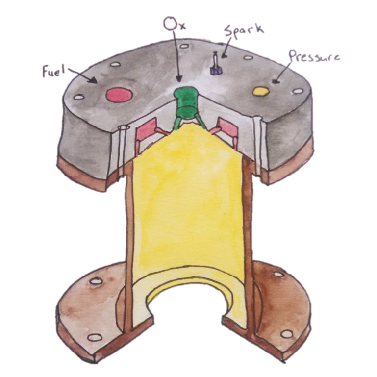
First pass cut away of gas generator

Safety

I just realized I have not talked at all about safety, so let’s remedy that today. Safety is very important in testing rockets and if you aren’t safe, there is always the chance that you won’t be able to keep testing, either through destruction of property, people, or yourself. So lets talk about how to make safety happen.

First things first: think, then act. Most problems are caused by acting too quickly or not thinking through the problems first. Frankly, most safety precautions are to protect you from a bonehead maneuver so step one is go at a decent pace and think your actions through.

Second: general shop safety. This has nothing to do with rockets, but most accidents, even in aerospace, happen in production. So always follow general good shop safety. Here are some of the most important points:

– No loose clothing, gloves, or long hair with power tools, especially lathes.
– Properly clamp down part before machining. And your hand is not any part of a proper clamp.
– Wear safety glasses and hearing protection.
– Learn how to use your tools before using them.
– Keep the shop clean and tidy.

Third: Proper personal protective equipment. With pressurized components, this is a minimum of safety glasses and hearing protection. For most chemicals, you want to wear nitrile gloves. With cryogenic propellants, you want some good cryo or thick leather gloves. I would say just don’t use anything toxic unless you are a professional, and then S.C.A.P.E. With Peroxide, make sure you wear an extra visor as it can blind you quick. And, in general, natural fibers, nothing synthetic as most of it it burns and melts so stick with cotton or wool.

Fourth: Test remotely. There should either be sufficient distance between you and the test or a thick wall – and sheet metal doesn’t count as a wall. A rough rule of thumb from the FAA  is that you should be at least 240 ft away from anything in line of site, and further if you have a large quantity of propellant. So maybe you should think about some walls, as 70 meters is a long way. Also, remote testing means the stand must be safe when you approach it even if you lose power. This means normally open vent valves and physical safe/arm switchs.

Fifth: Learn from your mistakes or, better yet, learn from others. You can either find an old timer to help you out for the first couple of runs or see if anyone else needs help. If all else fails, you can read Ignition! and some old accident reports.

This is obviously just an overview and we could go over safety all day and still have things to cover. Finally, listen to the safety guys and gals. They get a fair bit of shit in the NewSpace community, and while it is possible to be over safe and slow down development, it is easier to be cavalier and kill someone.

Main Run Valve

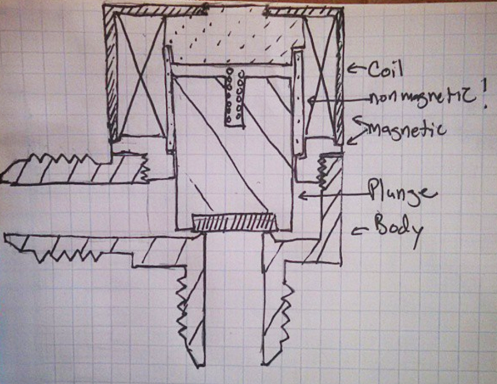
After running some numbers, we have changed our minds and are now planning on using a directly actuated solenoid valve for the main run valve. Our relatively small flow rate at only 0.5 lb/s of Liquid Oxygen means that the orifice we need is fairly small, only 0.22″ diameter. At this size, a ball valve is pretty bulky and trying to make a self-piloting solenoid also ends up being pretty heavy. Due to this, we are choosing to use a custom direct acting solenoid valve which is the most simple valve, having only 1 moving part and only requiring dc power. It comes at a weight penalty, but at only 0.7 lbs per valve, we are still under our main run line budget of 1.5 lbs.

To size a solenoid valve, first you need to size the orifice using the same mdot = CdA*sqrt(2*DP*rho) equation as in a liquid flow injector. Our valve is sized for a 10 psi drop on the LOX side. Then you run a bunch of calculations as shown on NASA SP-125 (pg 305 of the old version) to size the wires and coil. I would recommend not going thinner than 28 gauge wire, or over 600 coils if you are winding your own, as it gets tricky. We are using 8 Amps, 24 gauge wire, and 200 coils for the first pass.  It might be a bit high on the amperage (3.5 Amps are recommended for chassis wiring at 24 gauge), but it does push the weight and volume down. And we are pushing a lot of coolant through it. 🙂 This being said, the plan is nominally 4 cell LiPo batteries (14.8 V) for power, regulated to 12 V and 5 V for the electronics, but just used directly for the valves. We can also switch to 5 V power after the valve opens to minimize the power usage and heating.

We are planning on using neat PTFE for the seal with a Vespel and  carbon filled backup plan. PEEK is also a good cryogenic options. PTFE will creep over time, but it is a good choice for the hobbyist. I also have ordered some Nitrous Valves in the hopes of reusing the plungers and coils, but we will see how they work at cryo.

Below is an initial sketch of the valve we are going with the standard commercial orifice below poppet, as opposed to the more common aerospace inline solenoid valve to save money on machining and for ease of assembly. That is about it for now; I want to get the valve working before I have anyone else follow me down the rabbit hole of making your own valves.

Initial Valve Sketch

Actuated Valves

There are many valves used in rocketry, ranging from tiny gas pressurization solenoids to massive butterfly valves. In the field of small liquid rocket engines their are 3 main choices for actuated valves: solenoid valves, ball valves, and poppet valves. Each of these valves is useful and interesting and will get a post of its own in the future. Right now, lets just go over the basics.

-References:

SP-8094 – Liquid rocket valve components

SP-8097 -Liquid rocket valve assemblies

And the old SP-125 – Chapter 7

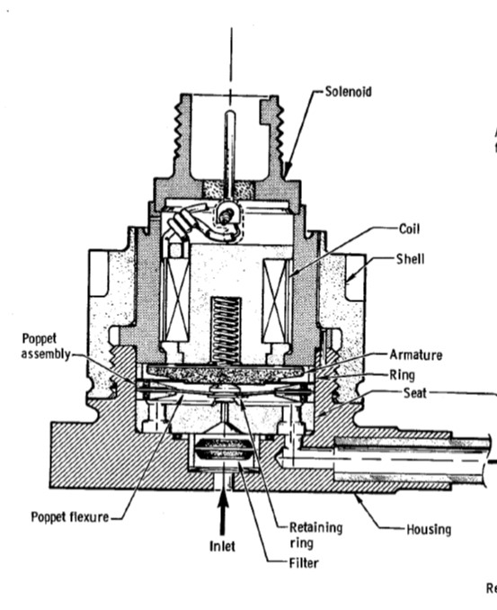
Solenoid valves – The most basic of valves, pretty much make a electromagnet to lift a seal off of an orifice. It is technically a poppet valve, but I classify direct acting solenoids as a different class. These valves are simple, require only power to work, and are readily available in many sizes. But they are relatively large and heavy, especially once your pressure is high or you need a large flow rate. Pretty much the best choice if your orifice is <0.125″ diameter.

Aerospace Solenoid from NASA SP-8094

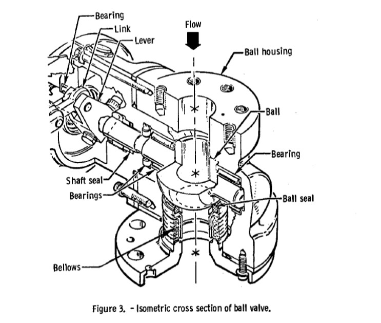
Ball Valves – A sphere with a hole though the middle – align the hole for flow, 90 degree turn to stop flow. These are the workhorses of valves, due to the fact that they are robust and, in the 0.25-3″ orifice, they are the lightest, most compact valve for the size. For most moderate sized rockets (i.e. between 200-50000 lbf), this is probably the main valve for you.

Aerospace ball valve from NASA SP-8094

Poppet Valves- A seal that is lifted off an orifice with a number of actuators, usually pneumatic, hydraulic, or electrical. These are simpler than ball valves, but they have an inherent 90 degree turn at the orifice. They are used in larger valve (6-10″ orifice) and balanced poppet versions are used for high pressure. These valves are also probably the easiest to make from scratch so they are quite popular with small amateur rocket groups.

The current plan for Earendel is a poppet valve that uses a pilot solenoid as an actuator. We will go over the specifics on Friday.

Injector Plan

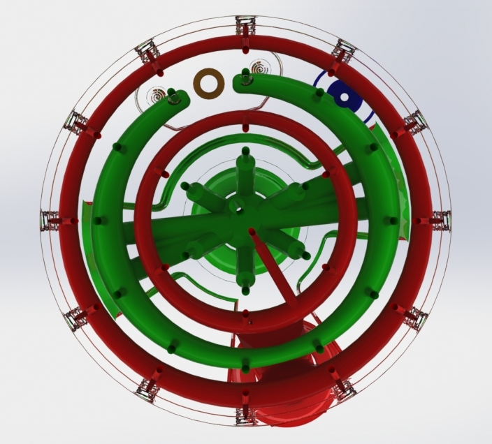
For Earendel, we are using liquid oxygen and isopropyl alcohol in a pressure fed engine at a relatively low pressure of 180 psi. These conditions make using impinging jet injectors a good first place to start.  Since the flow rate is relatively small and our orifice size is relatively large due to fabrication constraints, this means we will have a small number of elements and they should be unlike jets to promote mixing with the large orifice sizes.  In addition, we will have film cooling protecting the chamber wall so using unlike jets as the main element is fine. After running through some sizing, we end up with unlike impinging doublets as a functional design and the simplest of the impinging jet designs. You can see the injector manifold design below.

Doublet injector manifold from the chamber side with a clear body. LOX in green, Fuel in red.

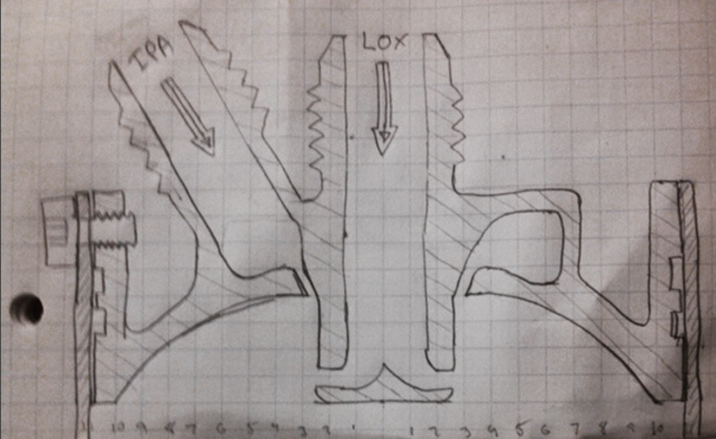
In addition to a unlike impinging jet, we are also going to experiment with a pintle design. This design will be simpler to manifold and potentially lighter and, thus, cheaper to 3D print. Given the relatively large unknowns in specifically sizing the pintle injector, we expect a few bad performers, either low performance or burning up walls, before we can get something to work.

Pintle injector cross section.

Injector Styles

There are 3 main injector element classification: non impinging jets, impinging jets, and hybrid. The elements are all varied in the method of atomization and mixing. All element types have advantages and disadvantages and the selection of an element type is a function of propellants and desired performance/robustness trade-off. Let’s first go over the different types of injector elements.

Non impinging jets – These are very common and are usually broken into two varieties: the showerhead and the impinging jet. Showerheads were one of the first injectors used in the V-2 and the Aerobee sustainer engine, and they are still used near chamber walls for film cooling. It is basically an array of axial jets and, as such, mixing and atomization are slow for these injectors, but overall uniformity can be good. Showerheads are not often used as main elements because of the low performance but, as I already mentioned, they are used near chamber walls for cooling. I have always wanted to use 3D printing to make a very fine array of showerhead elements to see how that would perform.

Concentric elements are broken into 2 major groups: shear coaxial, which is a tube of propellant A surrounding a rod of propellant B mixing by shear forces, and swirl coaxial, where one or both of the propellants are swirled leading to an injected cone of propellant. These are both very common in gas-liquid injectors, such as the RL-10 and the J2 LOX-H2, but they are hard to make work for a liquid-liquid injection and surprisingly complex as small geometric changes can have signification performance and stability effect.

Impinging Jets –  This is basically direct impingement of jets of propellants. Most of the mixing and atomization occurs at the impingement point of the jets and thus it is important to get the correct momentum ratios to achieve good mixing and atomization. This is done by either varying the pressure drop on the injectors or by adjusting the number of elements. The sizing of the correct momentum ratio is covered in various sources like NASA SP-809 pg 19. Usually these injectors are 1-on-1 (doublet element), 2-on-1 (triplet), 2-on-2 (quad), or 4-on-1 (Pentad).

Like-on-Like impinging is when jets of the same propellant combine and atomize, then mix downstream. This is a good and stable element, but doesn’t have quite as high efficiency as other options. Aligning elements for element to element mixing is key to performance. The elements are also used near chamber walls for reduced wall heating.

Unlike impinging is when jets of dissimilar propellants combine at the impingement points. These elements are an efficient and common choice for liquid to liquid injectors. They do have some stability and injector face heating issues, but are very quick mixing when made properly.

Hybrid Elements- Every other element type gets lumped in here, but it mostly consists of pintle elements and splash-plate injectors, amongst other weirder designs. Pintles are the most common of the other elements and have been used on many designs including the LEM descent engine and SpaceX Merlin engines. The design is a post with radial holes for propellant A at the end of the post and a tube of propellant forms at the base. The  design has some injector face heating and streaking issues, but it also has good performance and chamber wall comparability. It is also uncommon for usually having only 1 injector element per chamber.

Friday we will cover the Earendel rocket injector elements.

Relief Valves

Not a particularly exciting topic, but relief valves are very necessary to most rocket designs. They come in two major flavors: resettable (usually called relief valves) and non-resettable  (usually called burst disks). Both exist to protect your system from inadvertent over pressurization and the related failure: either burst, leak, or component failure.

The first thing you need to do is figure out where they go. A good rule of thumb is that if it can be closed off, it needs to have a relief valve. If you have a small line, <1/2″, and a propellant incapable of increasing in pressure (i.e. not a cryogenic liquid or a monopropellant), you can skip the relief valve in that section. On tanks or other large volume containers, you always need a relief device; if you look at commercial devices like dewars or gas bottles, you will see that they usually have relief valves or burst disks.

Burst Disks – I have always bought commercial burst disks and I would recommend purchasing the disks. They are hard to make as the exact thickness and mounting is important and you have to do batch testing to verify. Use burst disks on things you don’t expect to ever overpressure, like gas pressurant bottles, and be warned they can be VERY loud when they go off.

Relief valve – Lots of designs exist for these, both commercially from places like McMaster or Swagelok and designs from sources like NASA SP-8080. They are good if you need to adjust the relief pressure or if you expect frequent overpressuizations, like on cryogenic vessels. One note is they have some hystorisis, that is to say that if set to 100 psi, they will start hissing at 95 psi, flow fully at 100 psi, then vent down to 90 psi, or something similar.

Remember that safety is the most important thing when you are testing, because if you are not safe, you may not be around to finish the test. And while good procedures and 100% functional devices are good to strive for, relief valves are great to have for when something goes a little wrong with the system.

For reference this is what we are planning to use for relief devices:

– On the Earendel vehicle there will be a burst disk on the pressurant tanks (paintball style) and relief valves on both propellant tanks (McMaster Carr 9137K11).

– On the engine test stand, there will be a burst disk on the Nitrogen Cylinder, a relief valve and a burst disk on the LOX Dewar, relief valves on the propellant tanks, and a relief valve between the isolation valve and the run valve on the LOX run lines.

– On the igniter stand, there is only one relief valve and that is built into the GOX bottle.

3D Printing Rocket

Rockets are perfect for 3D printing technologies, well at least parts of rockets. Bodytubes, maybe not so much, control electronics, also a no, but rocket engines – there’s the ticket. They are relatively small parts with complex internal features and are manufactured in low quantity. Now for the bad news: they get very hot and very cold; they have small features; they are highly stressed. This means, in general, you can only use metal as a material. This limits us to DMLS, Casting and Infused metal.

DMLS is awesome; you send out a part as an stl file and you get a solid metal part back in a couple of weeks. While I have built various 3D printed parts, sadly none of them are mine to show, so instead check out this awesome work at Rocket Moonlighting. For rockets, DMLS materials are usually Inconel or PH 15-5 with other high temperature alloys such as Cobalt Chrome available as well as lightweight aluminum.

Infused metal is somewhat different from DMLS in that a porous version of the model is made, then infused with another alloy. Usually this is 420 SS fill with bronze. It is cheaper and quicker turn around than DMLS but at the expense of detail, only going down to around 40 mil holes vs DMLS 16 mil. Infused metal is also better with overhangs than DMLS. For these reasons, we are using Infused Metal for our igniter and injector, but if we were to make a regen engine we would probably use DMLS.

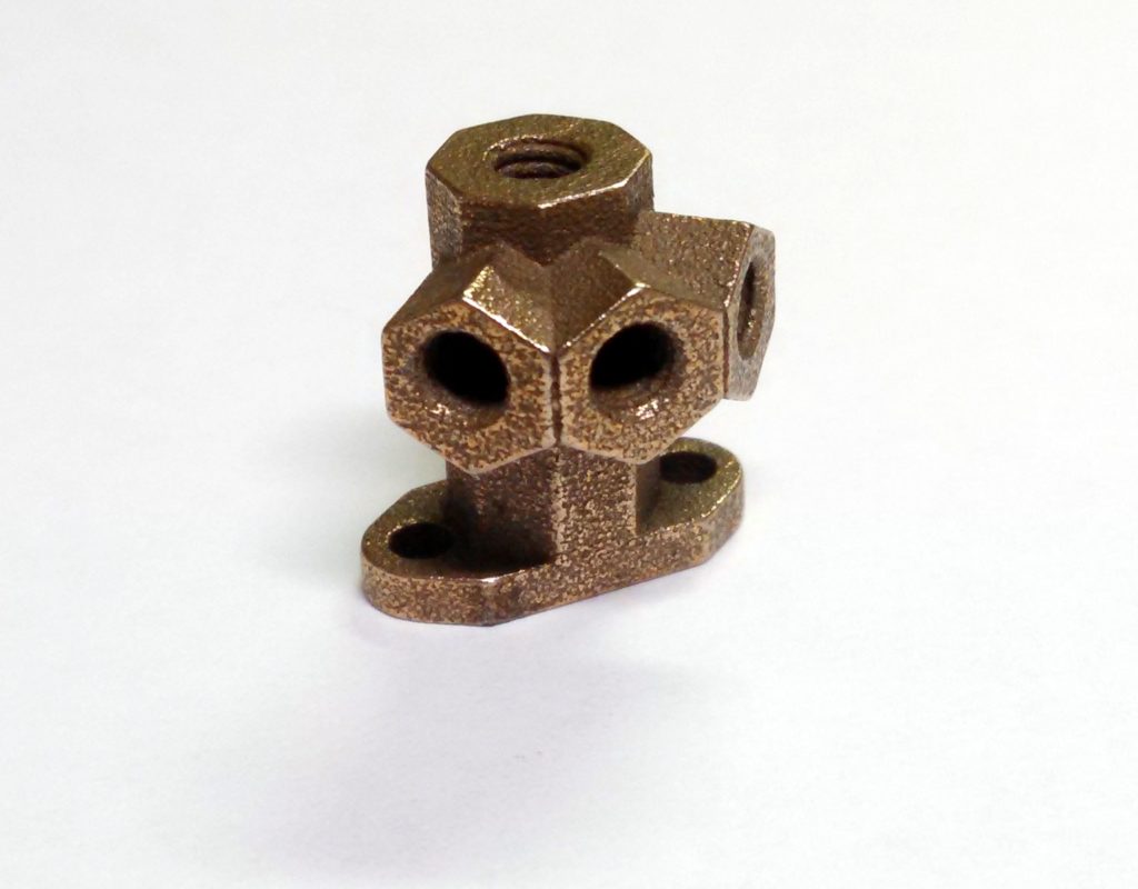
3D printed (infused metal) igniter as printed. Spark on top; from left to right fuel, pressure, oxidizer.

Casting is just like any other casting method, but it uses 3D printed wax. This technology has been around for decades now and is very common in low volume parts. It is a good technology, but it has a hard time dealing with long passages and thin walls, as well as only being commercially used with easy-to-cast alloys so we are not using it.

Rules of thumb:

If you can machine it, just machine it; it will probably be better, cheaper, and most likely faster.

Infused metal seems to build up more than the stl; allow for a ~4 mil growth.

You will have to tap most threads and, frankly, the surface finish is much improved by taping.

O-rings work fine with any of the 3D printed parts.

On DMLS, limit overhangs to 45 degrees or live with added supports during build.

ASK YOUR VENDOR about what post machining / supports they are adding.

Have a build direction in mind when you design the model; it really helps.

Surface finish isn’t great on DMLS or infused.

Long small holes are much more likely to clog than short small holes.

Make sure you have flats for post machining or wrench tightening.

That’s about it; give it a shot. Nothing says I’m living in the future like 3D printed metal parts arriving in the mail.

3D Printing – General

One of the technologies that will enable broad access to space is 3D printing and rapid prototyping in general. Friday we will cover the use of 3D printing specifically in rockets (mostly DMLS), but today lets just cover the basics of 3D printing.

At heart, 3D printing is manufacturing a component by adding material instead of subtracting material. Instead of removing material by machining away from a brick of material, small pieces of material are fused together to create a solid part. Most 3D printing works layer by layer by adding the material in one layer then stepping up to the next layer and continuing until the end of the file. The most common sorts of 3D printing are fusing filament, sintering, and stereolithography.

Filament Fusing – also know as FDM (Fused Deposition Modeling) – This uses a small filament which is extruded and heated to a liquid, then positioned drip by drip in the right location. Most DIY printers use this and, in general, it is great for prototyping as it is usually cheaper but with with some ridges and layer marks.

Sintering – also know as SLS (Selective Laser Sintering) – This uses a high powered laser to fuse powdered material together. A version of this called DMLS is used for metals. This is great for plastic prototypes and low volume production of all sorts. The main issues are cost for large volumes and getting the powder out of enclosed areas.

Stereolithography – This uses a laser to polymerize a photosensitive liquid. This works very well for surface finish and general build quality, but it is a brittle material so it is only used for fit check and models.

3D printing is a great technology for complex parts in low volumes. Since that is a great definition for rockets in general, we are going to use a fair bit of 3D printing in our designs.