Volute / Casing design

The main static structure of the pump is called a casing.  It has 3 main functions:

1- Feeds the fluid to the inducer/impeller. This is called the suction nozzle.

2- At the outlet of the impeller, the fluid is collected and then slowed down, converting velocity into pressure. This is called the volute.

3- The rest of the casing is devoted to various static mounts of seals, bearings, pressure taps, etc.

We will focus on the volute since the suction inlet is best done as a straight axial tube if possible, and the rest of the casing parts are highly dependent on the specific design.

Volutes are broken down into two major groups: plain volutes and diffusing vane volutes. In the former, the  impeller discharges into a a single volute that gradually increases area; then the fluid is diffused in a conical expansion at the volute exit. In the later, the impeller outlets into a series of vanes that do the majority of the diffusion and the volute acts as a fluid collection.  The diffusing vane is theoretically more efficient, but they are more complicated to design and produce and have worse off-nominal performance. In addition, for small pumps, there is an inefficiency associated with fluid drag on all of the vanes and, as such, plain volutes are all that we will talk about for pumps under 5000 lbf rockets.

Volute_sp125
Volute_sp125

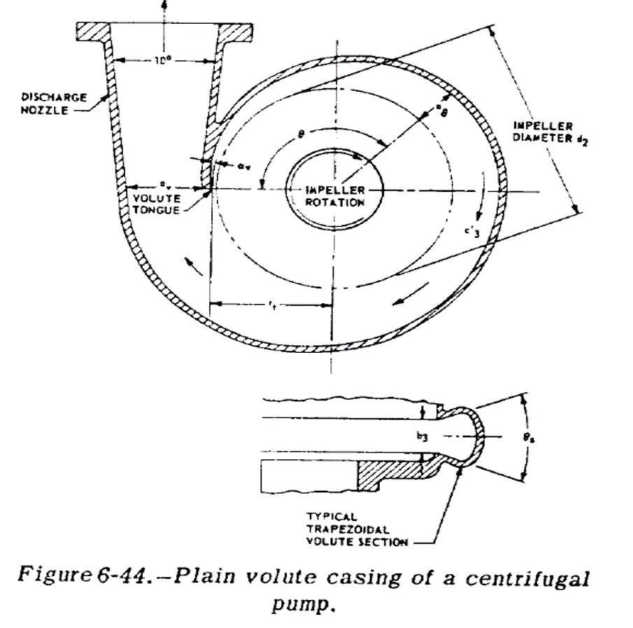
Plane volutes are fairly easy to design. b3, the volute width, is equal to 1.5-2x larger than the impeller width. Then you keep the average flow velocity of the volute constant  over angular location.

Average_Velocity = Kv * sqrt ( 2 * g * Pump_Head)

where Kv is between 0.15 and 0.55 and then

Average_Velocity = Pump_Flow_Rate * Theta * Pump_Flow_Rate / (Area_Volute_Throat * Area_Volute_Section)

The minimum volute diameter for the volute radius should be 5-10 percent larger than the impeller diameter. Then, for the discharge nozzle, expand the flow at between 10 and 12 degrees until the flow velocity is equal to whatever you want for the nominal tubing flow speed.

And those are the basics of a volute. Next post, we will put everything together for a simple pump design.

Inducer Design

In the design of a rocket pumps, one of the biggest drivers is making the pumps as small and thus lightweight and packagable as possible. The main issue is that a small pump inlet has a relatively high velocity and, thus, lower pressure. When the fluid then hits the impeller, the pressure drops further on the back sides of the pump blades. When this pressure drops below the vapor pressure of the pumped liquid, a gas bubble is formed and this process is known as cavitation. This is bad for the pump for two main reasons; the first is that the gas bubble formation can cause high stress and actually destroy the impeller. The second is the gas bubble, with much lower density than a liquid, blocks the flow leading to lower pressure rise and flow rate.  To get around this problem, a inducer is commonly added to the inlet of a pump impeller.

An inducer is pretty much a single stage axial pump, usually designed to pressurize the fluid to 10% of the total pump pressure and they are designed to work even with a small amount of cavitation. NASA SP-125 actually has all of the relevant design equations (sample calculation 6-7), so I won’t go over them all again in this post.

Inducer design from SP-125

The basics are that you calculate a mean inducer tip speed:

Mean_Tip_Speed = sqrt ( Head_Rise * gravity / Inducer_Head_Coefficient)

with the  Inducer_Head_Coefficient being an experimental number between 0.06 and 0.15.  From the mean tip speed, you can then calculate the mean diameter and, thus, the inner and outer inducer diameter. Then you calculate the angle of attack at the the front edge using:

Flow_Angle = atan ( Inlet_Axial_Velocity / Inlet_Outer_Tip_Speed)

You then make the inlet vane angle between 1-4 degrees higher than the flow angle. You then take this tip angle and set all of the inlet angles using:

Diameter_A * tan (Angle_Of_Attack_A) = Diameter_B * tan (Angle_Of_Attack_B)

Now, for the outlet, you need to calculate the outlet flow angle using:

Outlet_Flow_Angle = atan ( Outlet_Axial_Velocity / (Mean_Outlet_Peripheral_Speed – Mean_Outlet_Tanjential_Speed))

Then you set the outlet angle equal to the Outlet flow angle + 1 degree to account for real world effects. The final thing is to choose a number of blades, usually 3-5 based on desired solidity, and you are good to go.

As you can see, I glossed over some steps, but with this and SP-125, it is actually easier to design than a impeller so good luck if you give it a go.

Turbopump Isp

In some previous posts, I have added some Isp’s and, if you have been looking closely, they seem a little lower than expected. This is because I have been looking at gas generator cycles and in these cycles some small percentage of the flow goes thru a gas generator and does not go through the main engine. Due to a bunch of reasons like not wanting to burn the pump up in seconds and needing pressure to drive the turbines, the flow is at a much lower temperature and pressure than the main engine. To account for this we need to:

Estimate the amount of flow in the Turbine – This is a simple energy balance equation that usually comes down to around 3% for a 1000 psi LOX RP-1 engine.

Calculate the Isp from the Engine (easy, lets assume 270 s SL) and the turbopump. Now for temperature ~1000 F and low pressure, ~40 psia, so they have Isp’s of around 80 seconds.

So now you throw them into the equations:

Isptot = (1-%turbine) * IspMainEngine + (%turbine) * IspTurbine.

Or, for our example, = (0.97 * 270 + 0.03 *  80) = 264 s.

As you can easily see, Isp is significantly lower ~2.5% and this is with fairly moderate pressure. As you can image for a certain cycle, there is an optimum pressure; higher isn’t always better as far as gas generator cycles are concerned.  This being said, for LOX RP-1, the tipover point with reasonable efficiencies is about 1500-2000 psi PC, so if you look around you see a lot of engines and studies  for GG at around 1200 psi. Higher than this requires multiple impellers and isn’t worth the extra complexity for the very negligible gains of the next couple hundred psi.

Propellant Tanks – Case Study

For this post, I’ll go over the basic design of the fuel tank on the Earendel Sounding Rocket.

Step one in any design is the requirements, so here we go:

– 9.6 kg of Isopropyl Alcohol

– 220 psi tank pressure

– 2.5 x Factor of safety

– 3% Ullage (% initial gas) , 3% residual propellant (unburnt at the end)

– For a Sounding Rocket so cylindrical form factor

With these requirements, let’s get started with sizing the propellant tank. The first step is the volume of the tank. At a density of 785 kg/m^3, that gives us a propellant volume of 746 in^3 and a tank volume of 791 in^3. If we want a 4-1 cylinder, that gives us a 6.25″ diameter. But to match up with a standard composite tube of 6.02″ ID, we will choose 6.02″ as the ID. Now, for the endcaps, we choose a 60% ellipse as needing roughly the same wall thickness as the sidewall of the cylinder, as you can see in the chart below.

Endcap stress from SP-125

Now this gives us a tank with a 6.02″ ID wall, 25.4″ tall, with 1.8″ tall endcaps. You can see the rough size below and it looks pretty reasonable.

Rough Tank Sizing
Rough Tank Sizing

Now a stress analysis for the wall thickness. We will use aluminum 6061-T6 as it is common in 6″ pipes and tubes as well as rods for the endcaps. It has a 42 ksi ultimate strength, and a 35 ksi yield so we can just use the ultimate. The sidewall calculation is fairly easy with:

42 ksi / 2.5 = 220 psi * (6.02″ / 2) / t      ==>  thickness = 0.0394 that we will just round to 0.040″

For the endcap, using the modifier from SP-125 Fig 8-7 of 0.92 and equation 8-19, we get 0.0344″ for the ellipse thickness. Let’s just round that up to 0.040″ as well to give us margin on any discontinuities.

Now for attachments. There should be a bulkhead on both of the endcaps; let’s make it 2.5″ diameter as, from my past experience, that is about as small as is useful for multiple ports. We could also choose to machine ports directly into the tank. This is more expensive and harder to machine and clean, but with the benefit of less seals and a robust mount. So using our flat plate stress analysis, and assuming a bolt diameter of 3.0″, that gives us a thickness of  0.075″. The pressure load is good for 3900 lbf with the 2.5x FoS so that is either 20 #4-40 screws or 14 #6-40 screws or 9 #8-32. So we will just use 10 #8-32 screws.

And the last attachment is the endcaps, which we will use bolts for again. Since the stress area will be around 5.5″ after the bolts go in, that is a load of 13,100 lbf. We want around 20 bolts so that means we have to use 1/4-28 bolts, once again assuming we have Al-6061 bolts.

One word about aluminum bolts: The most common bolt is 7075-T73 or 2024-T4 which are OK for cryogenic service and are stronger than 6061. So we are being conservative with the bolt strength. Please double check your vendor though because some bolts are 3000 or 1000 series alloys which are very weak by comparison.

Now for the seals. There are two of them: the bulkhead and the endcap. We will use viton o-rings as they are cheap, available, and work very well. We will also use 1 O-ring per seal; there is no redundant seal, which is fine for our application, but sometimes frowned upon in high risk fault intolerant systems. I highly recommend the Parker O-ring handbook. In this case, I used it and will be using a face seal gland with a #38 O-ring on the bulkhead and a #160 O-ring on the endcap.

Initial design flange seals

This is the end of the initial design. At this point, you will want to model the tank, check its weight, run a stress analysis, and see how it lines up and mounts with other structures in your system.  Good luck, and be prepared for the inevitable redesign!

3D Printing – General

One of the technologies that will enable broad access to space is 3D printing and rapid prototyping in general. Friday we will cover the use of 3D printing specifically in rockets (mostly DMLS), but today lets just cover the basics of 3D printing.

At heart, 3D printing is manufacturing a component by adding material instead of subtracting material. Instead of removing material by machining away from a brick of material, small pieces of material are fused together to create a solid part. Most 3D printing works layer by layer by adding the material in one layer then stepping up to the next layer and continuing until the end of the file. The most common sorts of 3D printing are fusing filament, sintering, and stereolithography.

Filament Fusing – also know as FDM (Fused Deposition Modeling) – This uses a small filament which is extruded and heated to a liquid, then positioned drip by drip in the right location. Most DIY printers use this and, in general, it is great for prototyping as it is usually cheaper but with with some ridges and layer marks.

Sintering – also know as SLS (Selective Laser Sintering) – This uses a high powered laser to fuse powdered material together. A version of this called DMLS is used for metals. This is great for plastic prototypes and low volume production of all sorts. The main issues are cost for large volumes and getting the powder out of enclosed areas.

Stereolithography – This uses a laser to polymerize a photosensitive liquid. This works very well for surface finish and general build quality, but it is a brittle material so it is only used for fit check and models.

3D printing is a great technology for complex parts in low volumes. Since that is a great definition for rockets in general, we are going to use a fair bit of 3D printing in our designs.