
As it turns out, I am a better engineer than I am a businessman or website manager, and the latter has appeared to cause me some trouble. The Project Earendel website went down and all of the data is lost to the internet; I have just begun to put all of the information back into place. This will take a while and there will unfortunately be gaps in the blog from the Internet Wayback Machine – and the fact that I do not have a local backup of the writing, only the images. I’ll do my best and hopefully by the end of the month the website will be back up to snuff.
News
A Modest Non-Rocket Launch Proposal
On the aRocket list, we get the occasional individual proposing methods to put payloads into space using mega-structures instead of rockets. This is in response to the suggestion of dropping the payload down and out a hole though the center of the Earth using a drop tower, though it could be rewritten for most novel space launch concepts.
***
A modest proposal for preventing the theorist from being a burden to this list, and for making a non-rocket space-launch that is beneficial to the publick.
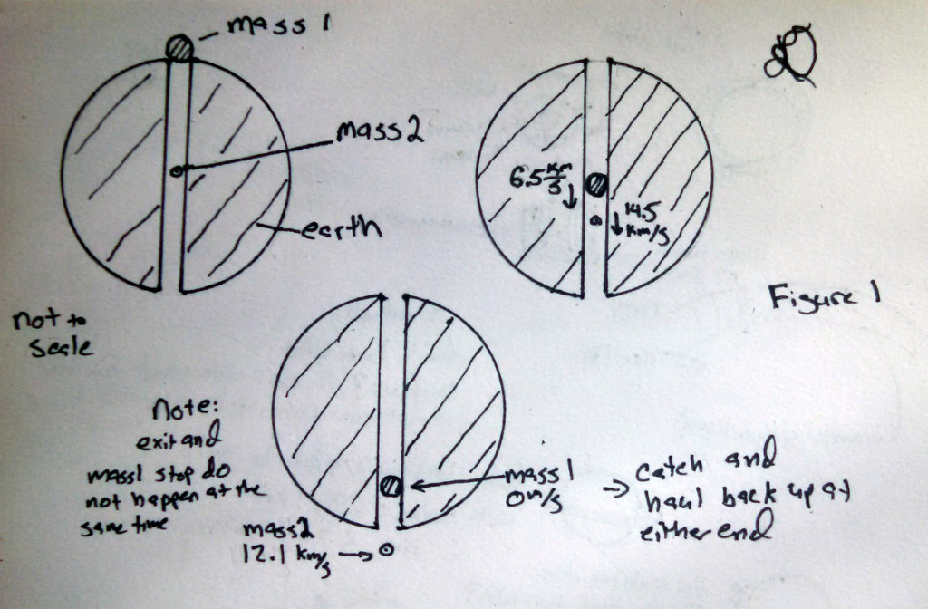
You don’t need a drop tower; what you need is an elastic collision at the center of the Earth. Imagine a mass of weight 1 kg at the center of the Earth and a mass of 10 kg dropped from the Earth’s surface down a tube. At the collision, the 10 kg mass is travelling 8 km/s. After a perfectly elastic collision, the devising of which is left as an exercise to the reader, The 10 kg mass is travelling at 6.5 km/s and, more importantly, the 1 kg mass is traveling at 14.5 km/s! This speed decreases to 12.1 km/s at the surface which is more than enough speed to escape the Earth (11.2 km/s escape velocity). Low drag, converting velocity into the desired direction, and aerothermal heating are left as exercises to the reader. See Figure 1.
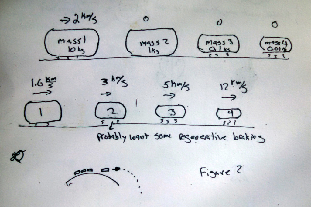
Now, you may ask, why bother going to the center of the Earth at all. Isn’t it a deep, hot hole and, thus, quite hard to drill? Why not just string together our perfect momentum transfer system into a series of bounces at the Earth’s surface to achieve high velocity. If we start with a moderate velocity of 0.3 km/s, easily achievable, and our 10-1 mass ratio, we achieve orbital velocity in 6 bounces! Unfortunately, at a mass ratio of 100000-1. Well, if we increase the initial speed to 2 km/s, still in the relatively easy range, we only need 4 bounces for escape velocity with a 1000-1 mass ratio. Hmm. Let us drop the mass ratio down to 2-1. Now we need 7 bounces but we achieve a 32-1 mass ratio which is not bad at all. See Figure 2.
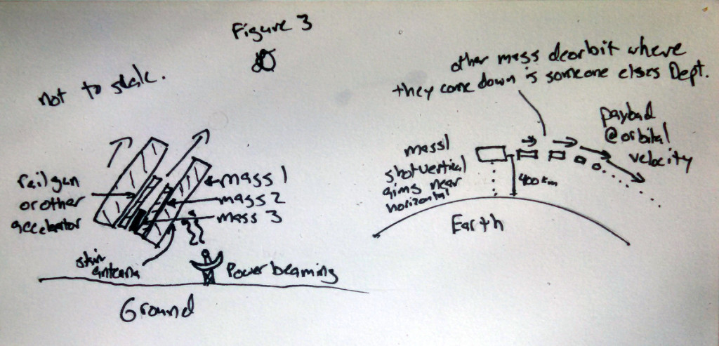
Perfectly elastic collisions are hard to achieve in large objects, but we can mimic them by throwing mass 2 off of mass 1; we just need a rail to accelerate mass 2 located on mass 1 and, instead of using stationary power, we have to beam the power to the moving mass 1. Beaming high power is left as an exercise to the reader. Now we can aim the masses and don’t have to stick to a fixed track, so we can achieve any given orbit! See Figure 3.
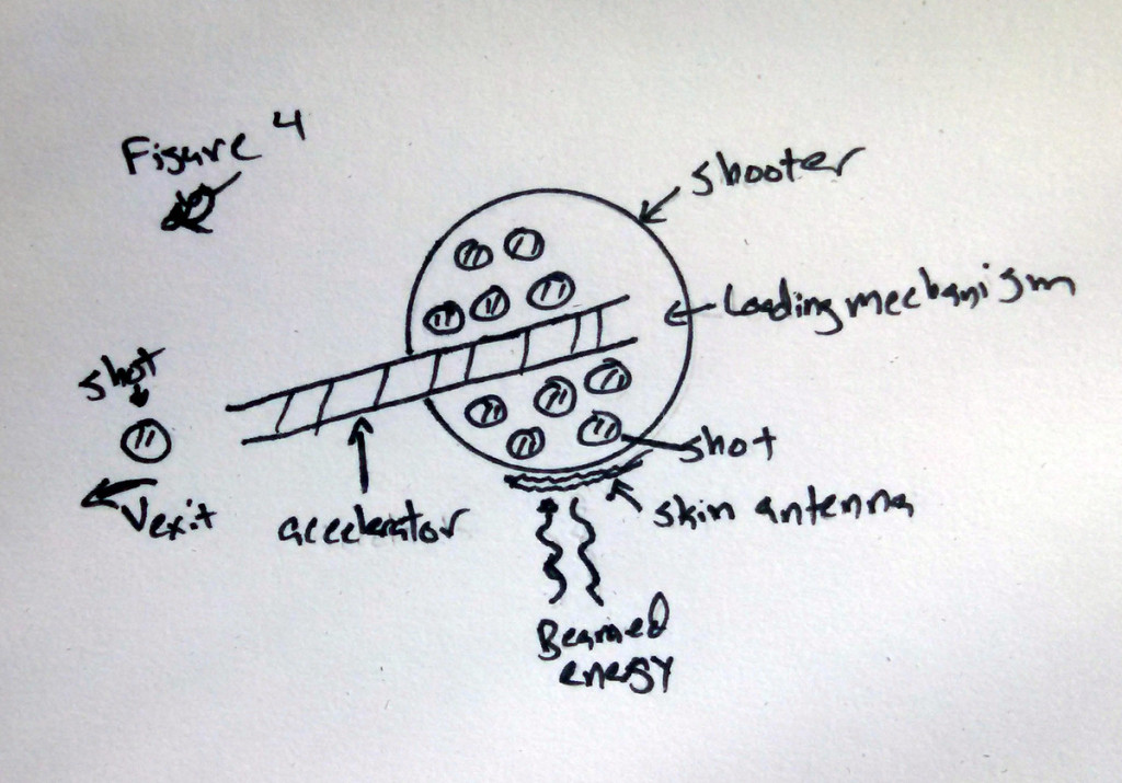
But we have to build all of these masses and mass drivers and that could be expensive. If we would stop and think for a moment, we see that we could just build one large flying mass and throw a number of smaller masses off of it. On the plus side, we lose weight as we shoot out mass which makes each additional mass add more velocity. If we stick with our 2 km/s mass driver, we have to go down to a 20-1 mass ratio (initial mass ratio) and it takes 19 pushes to achieve orbital velocity with a 20-1 mass ratio. But we only need one rail to achieve this! See figure 4.
Beaming power is hard and unproven technology. But we could generate the power on board, either through nuclear or chemical reaction. This might take up a fair bit of the mass on the flying shooter mass but, it if all else fails, we can always just up the mass ratio to accommodate the generator. Also, to keep the generator from having to store energy between shots, the shot mass should be made as small as possible. Deriving the ideal shot out mass for final speed when using a very large number of small shot masses is left as an exercise to the reader. See Figure 5.
But wait! Two more finishing touches and we might make a practical system yet. It may be possible to find a way for the shot mass to generate the energy before it is thrown overboard. We can make the shot out of a variety of chemicals that generate energy when combined, for example the thermite reaction Fe2O3 + 2 Al → 2 Fe + Al2O3. + heat. Better yet, many of these reactions have gaseous by products and gasses are easy to accelerate using a simple converging diverging nozzle. For example, O2 + 3 H2 = 2 H2O+ H2 + heat which, at the reaction temperatures, are gasses the can be accelerated easily to 4 km/s which rather simplifies the shot accelerator design. Determining the optimal chemicals is left as an exercise for the reader. See Figure 6.
I profess that I have not the least personal interest in endeavoring to promote the necessary work; having no other motive than the public good of my country, the advancement of our technology, providing for the satellite industry, relieving the cost burden on space access; and giving some pleasure to the inevitable sponsoring government agencies.* I think I shall now go forth and gather a group of devoted amateurs to develop this crucial technology. Perhaps create an email list for people devoted to find affordable, safe, and accessible methods of building such a device. I will call it the amateur stored energy shot reaction driver society or aSesrds for short. Anyone who wishes to use these ideas for the betterment of society can have them for a single penny.
Lloyd
* Paraphrase from A modest Proposal, Jonathan Swift
***
PS: The system name of aSesrds is somewhat unwieldy and one Benjamin Brockert has suggests a superior alternative. In his words:
“If each of the initial elastic masses are made of convenient in-situ earthen resources, we might call each a ‘rock’ from its Terran origins.
If then we make the whole system smaller, as you propose, the unit item might be called the same name with a diminutive suffix, perhaps the ‘rock-ette’. As is in favor in these times, a phonetic simplification could be something like ‘rocket’.”
Volute / Casing design
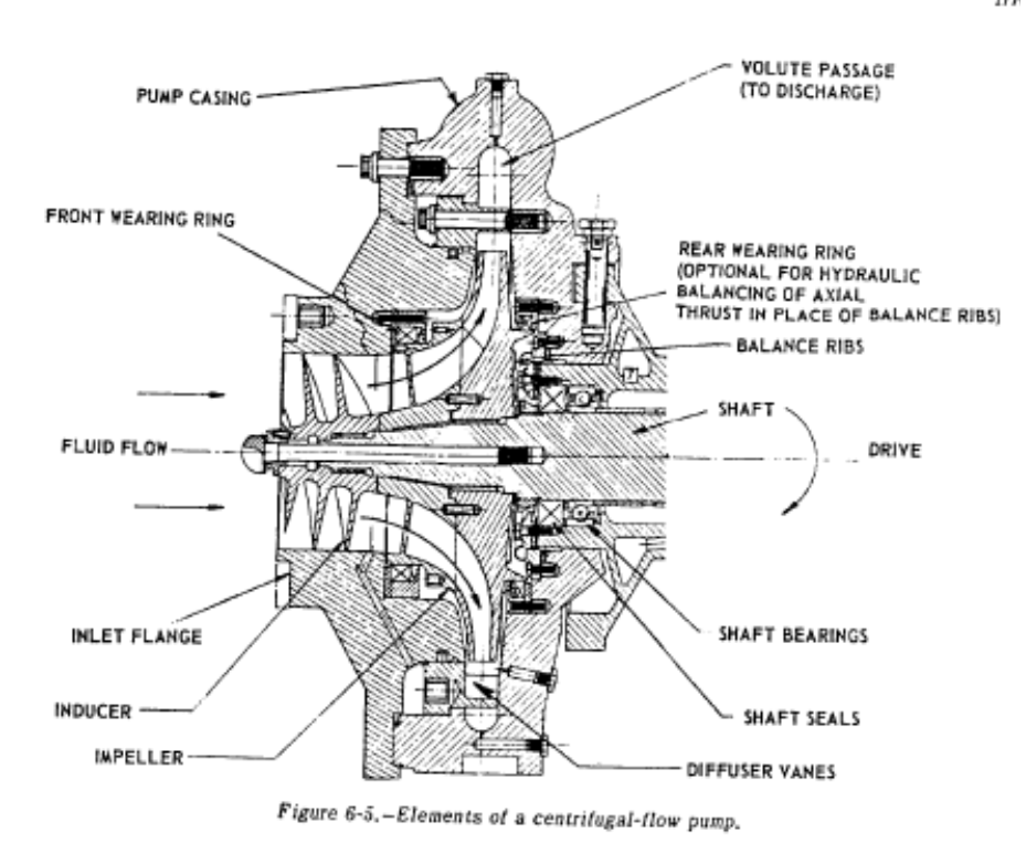
The main static structure of the pump is called a casing. It has 3 main functions:
1- Feeds the fluid to the inducer/impeller. This is called the suction nozzle.
2- At the outlet of the impeller, the fluid is collected and then slowed down, converting velocity into pressure. This is called the volute.
3- The rest of the casing is devoted to various static mounts of seals, bearings, pressure taps, etc.
We will focus on the volute since the suction inlet is best done as a straight axial tube if possible, and the rest of the casing parts are highly dependent on the specific design.
Volutes are broken down into two major groups: plain volutes and diffusing vane volutes. In the former, the impeller discharges into a a single volute that gradually increases area; then the fluid is diffused in a conical expansion at the volute exit. In the later, the impeller outlets into a series of vanes that do the majority of the diffusion and the volute acts as a fluid collection. The diffusing vane is theoretically more efficient, but they are more complicated to design and produce and have worse off-nominal performance. In addition, for small pumps, there is an inefficiency associated with fluid drag on all of the vanes and, as such, plain volutes are all that we will talk about for pumps under 5000 lbf rockets.
Plane volutes are fairly easy to design. b3, the volute width, is equal to 1.5-2x larger than the impeller width. Then you keep the average flow velocity of the volute constant over angular location.
Average_Velocity = Kv * sqrt ( 2 * g * Pump_Head)
where Kv is between 0.15 and 0.55 and then
Average_Velocity = Pump_Flow_Rate * Theta * Pump_Flow_Rate / (Area_Volute_Throat * Area_Volute_Section)
The minimum volute diameter for the volute radius should be 5-10 percent larger than the impeller diameter. Then, for the discharge nozzle, expand the flow at between 10 and 12 degrees until the flow velocity is equal to whatever you want for the nominal tubing flow speed.
And those are the basics of a volute. Next post, we will put everything together for a simple pump design.
Inducer Design
In the design of a rocket pumps, one of the biggest drivers is making the pumps as small and thus lightweight and packagable as possible. The main issue is that a small pump inlet has a relatively high velocity and, thus, lower pressure. When the fluid then hits the impeller, the pressure drops further on the back sides of the pump blades. When this pressure drops below the vapor pressure of the pumped liquid, a gas bubble is formed and this process is known as cavitation. This is bad for the pump for two main reasons; the first is that the gas bubble formation can cause high stress and actually destroy the impeller. The second is the gas bubble, with much lower density than a liquid, blocks the flow leading to lower pressure rise and flow rate. To get around this problem, a inducer is commonly added to the inlet of a pump impeller.
An inducer is pretty much a single stage axial pump, usually designed to pressurize the fluid to 10% of the total pump pressure and they are designed to work even with a small amount of cavitation. NASA SP-125 actually has all of the relevant design equations (sample calculation 6-7), so I won’t go over them all again in this post.
The basics are that you calculate a mean inducer tip speed:
Mean_Tip_Speed = sqrt ( Head_Rise * gravity / Inducer_Head_Coefficient)
with the Inducer_Head_Coefficient being an experimental number between 0.06 and 0.15. From the mean tip speed, you can then calculate the mean diameter and, thus, the inner and outer inducer diameter. Then you calculate the angle of attack at the the front edge using:
Flow_Angle = atan ( Inlet_Axial_Velocity / Inlet_Outer_Tip_Speed)
You then make the inlet vane angle between 1-4 degrees higher than the flow angle. You then take this tip angle and set all of the inlet angles using:
Diameter_A * tan (Angle_Of_Attack_A) = Diameter_B * tan (Angle_Of_Attack_B)
Now, for the outlet, you need to calculate the outlet flow angle using:
Outlet_Flow_Angle = atan ( Outlet_Axial_Velocity / (Mean_Outlet_Peripheral_Speed – Mean_Outlet_Tanjential_Speed))
Then you set the outlet angle equal to the Outlet flow angle + 1 degree to account for real world effects. The final thing is to choose a number of blades, usually 3-5 based on desired solidity, and you are good to go.
As you can see, I glossed over some steps, but with this and SP-125, it is actually easier to design than a impeller so good luck if you give it a go.
Pump Sizing
There is currently a fair bit of discussion on the aRocket list about amateur electric and turbine powered pumps, so I thought it would be helpful to go over some basic pump sizing work. Then maybe next post I will show a specific pump impeller design example.
First things first, in order to size a pump you need 4 basic numbers: mass flow rate (mdot), pressure rise (deltaP), fluid density (rho), and RPM. If you don’t have these numbers, then go ahead and make them up now. Now, what we want to calculate is pump specific speed (Ns) and pump power. Pump specific speed is a quasinondimensional number (I’m using English units for Ns and bastard for elsewhere – sorry metric folks!) that should help us identify the pump type and geometry that we should be using and power is useful in selecting our driving motor.
Step 1: calculate volumetric flow rate in GPM
GPM = mdot (kg / s) / rho (kg / m^3) * 60 * 264
Step 2: Calculate head rise
Head rise (ft) = deltaP (psi) / rho (kg / m^3) * 144 / (2.205 * 0.305^3)
Step 3: Calculate specific speed
Ns = RPM * 1000 * GPM^0.5 / Head^0.75
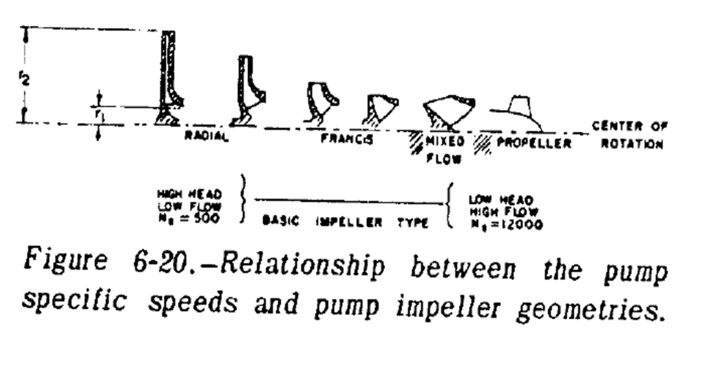
And you should get a number between ~200 and 20,000. You then take the number and compare it to the plot below to choose an appropriate pump type. Radial pumps with around an Ns of 1000 and axial pumps with NS of ~10000 are probably the easiest pumps for an amateur to get up and running. In our case, we would rather do the radial because we need the pressure rise.
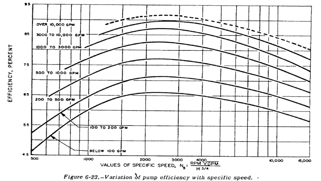
Now, to calculate pump power, we need efficiency; luckily for us, there is a handy chart for that, also from SP-125. Take your GPM and Ns and you get an efficiency. Pretty easy, right? Well, for an amateur, I would say knock off an extra 10% and, for a damn good pro, you might get an extra 10% as these are just standard values. If you don’t like your efficiency, modify your pressure rise or RPM.
You can see that with any pump for a rocket under 100 GPM, or ~10 klbf, you really want Ns up to 1500-4000 for any sort of efficiency.
Now to calculate power.
Step 1: Fluid Power
Power_Shaft (Watts) = Mdot (kg/s) * 9.8 m/s * Head (ft) / 3.28 / Pump_Efficiency
That is the power that you reed to drive the impeller. If you assume an extra 10% power for bearings and seals, you have your pump roughed out.
Impeller Sizing
For the sake of this discussion, we will only consider centrifugal pumps – but if you are doing rockets and not using hydrogen, that is a good assumption. The pump on a rocket is broken up into 3 main parts: the inducer, the impeller, and the volute. The inducer is a low pressure rise pump that limits cavitation in the impeller; it is only necessary for high specific speed pumps, which is most of rocketry. The impeller is the main pumping element and is effectively a paddle wheel that takes slow moving fluid from the core and ejects it at high speed from its sides. The volute takes the high speed fluid and slows it down, converting the high speed to high pressure. All told, they make up a rocket pump, but we will just go over the basic sizing of the impeller and not worry about fun things like velocity triangles today.
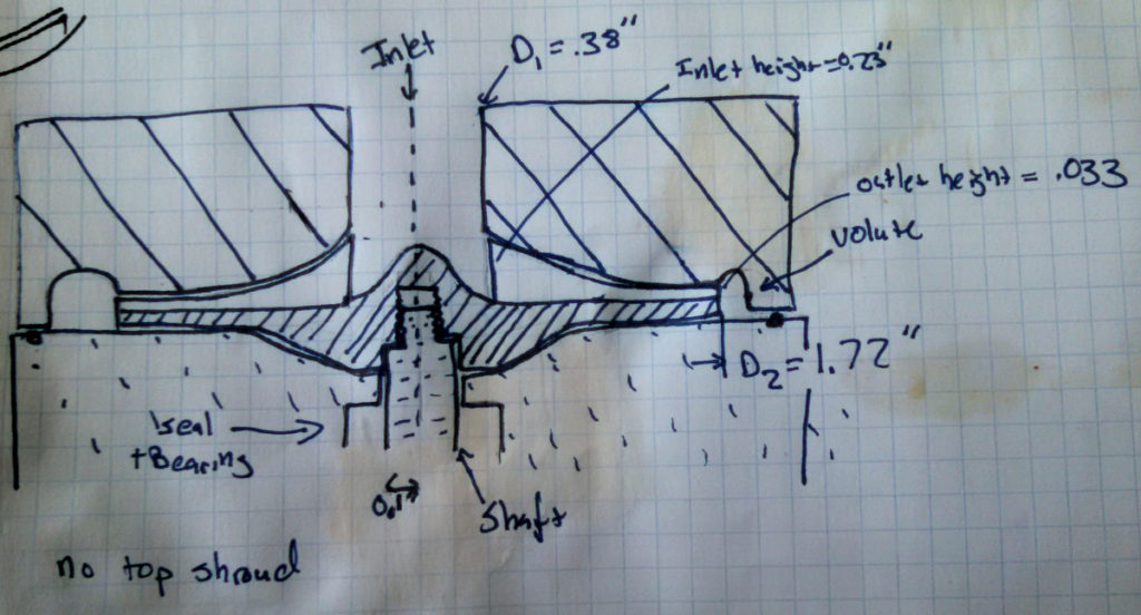
Once you have done all of the basic sizing that we talked about last week, you have the basic properties of the pump system but no sizes. If you want to do a detailed pump sizing, I would recommend NASA SP-125 and SP-8109 as it is a bit more complicated than a blog post. But, today, let’s get you the two biggest pieces of information you need: outlet diameter and outlet height. These are useful to determine the mass and manufacturability of the pump, as outlet height is usually the smallest geometry and diameter of the impeller and, thus, the volute determines most of the mass properties for a pump.
The process for exit diameter is iterative and consists of the following equations (everything in ft, GPM, ft/s, and RPM):
Head_Coefficient = gravity * Head_Rise / (Tip_Velocity)^2
Specific_Diameter = Tip_Diameter * Head_Rise^0.25 / Flowrate^0.5
Tip_Diameter = Tip_Velocity / (pi * RPM)
Then use the plot below.
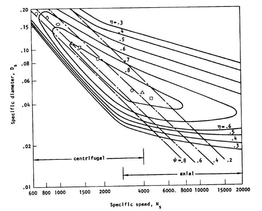
So now iterate on that for a bit, and we have the outlet diameter.
To find the exit height the equation is:
Exit_Height (in) = Flow_Rate(GPM) / (3.12 * pi * exit_diameter(in) * exit_radial_velocity(ft/s) * contraction_factor)
where the contraction factor is usually estimated as 0.9 and the radial velocity can be estimated by:
exit_radial_velocity = flow coefficient * tip_velocity
Flow coefficient is usually between 0.01 and 0.15 and can be found on the plow below.
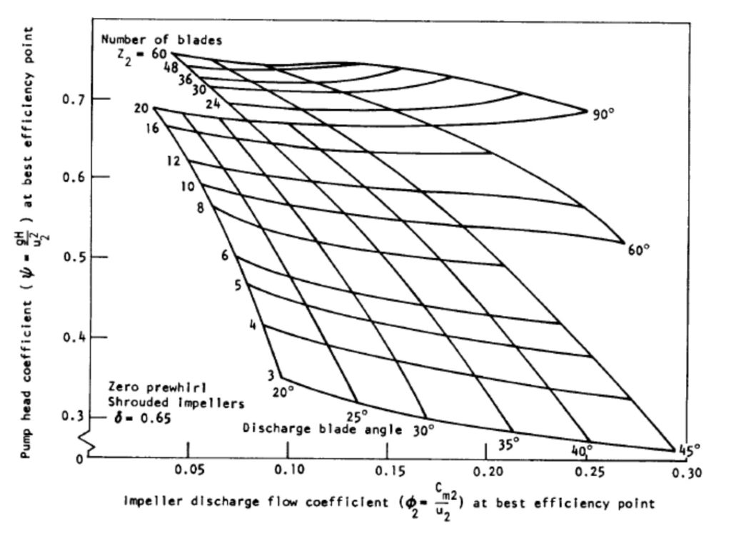
I hope this has all been useful in determining how to size a impeller; obviously the final design is more complicated with flow angles, but these basics should point you in the correct direction.
Turbopump Isp
In some previous posts, I have added some Isp’s and, if you have been looking closely, they seem a little lower than expected. This is because I have been looking at gas generator cycles and in these cycles some small percentage of the flow goes thru a gas generator and does not go through the main engine. Due to a bunch of reasons like not wanting to burn the pump up in seconds and needing pressure to drive the turbines, the flow is at a much lower temperature and pressure than the main engine. To account for this we need to:
Estimate the amount of flow in the Turbine – This is a simple energy balance equation that usually comes down to around 3% for a 1000 psi LOX RP-1 engine.
Calculate the Isp from the Engine (easy, lets assume 270 s SL) and the turbopump. Now for temperature ~1000 F and low pressure, ~40 psia, so they have Isp’s of around 80 seconds.
So now you throw them into the equations:
Isptot = (1-%turbine) * IspMainEngine + (%turbine) * IspTurbine.
Or, for our example, = (0.97 * 270 + 0.03 * 80) = 264 s.
As you can easily see, Isp is significantly lower ~2.5% and this is with fairly moderate pressure. As you can image for a certain cycle, there is an optimum pressure; higher isn’t always better as far as gas generator cycles are concerned. This being said, for LOX RP-1, the tipover point with reasonable efficiencies is about 1500-2000 psi PC, so if you look around you see a lot of engines and studies for GG at around 1200 psi. Higher than this requires multiple impellers and isn’t worth the extra complexity for the very negligible gains of the next couple hundred psi.
NASA VCLS Mass Budget
Last time around I gave some numbers for a VCLS (Venture Class Lauch Service) vehicle; today we’ll cover a bit more of the mass budget specifics.
The basis of a mass budget is the deltaV equation: deltaV = Isp * g * ln (Minitial / Mfinal). Now deltaV is our desired velocity, Isp is the engine performance, and what we are looking at today is the mass ratio of initial mass over final mass. If we only know deltaV, Isp, and g, we cannot solve this equation as we have two unknowns, but we know a bit more information than that.
Minitial = Mpayload + Mpropellant + Mdry
Mfinal = Mpayload + Mdry
PMF = Mpropellant / (Mpropellant + Mdry)
Now with all of these equations, we know the payload mass and we have to estimate PMF (propellant mass fraction). Just like Isp is a measure of performance of the engine, PMF is a measure of performance of the structure. PMF is historically around 0.93 for a First Stage and 0.89 for an Upper Stage, but obviously this is somewhat variable and a function of propellant and stage cycle.
A good reference for PMF is Propellant Mass Fraction Calculation Methodology for Launch Vehicles and Application to Ares Vehicles.
So I used 0.92 for the first stage and 0.88 for the upper stage, taking a 1% hit for the smaller scale effect (damn you cube square law and electronics actually having mass).
Once we calculate the masses, we should do a quick estimate for tanks and engines which are the major players in the mass of the vehicle. Doing this, I find that the First Stage tanks and engine are 60% of the dry mass budget and the upper stage is 75% of the dry mass budget. Just based on historical numbers and previous work, I think at this stage somewhere between 60-70% is reasonable; so that is saying that our upper stage needs to decrease its PMF estimate or improve the tanks or have a low chance of eventual success. This is why initial sizing is important: you need to to be able to understand the system and where the margins are thin to effectively build up and test the rocket.
So later this week, in continuing the VCLS, I’ll cover turbopump rocket Isp calculations.
NASA Venture Class Launch Service
NASA announced a draft RFP for a vehicle that launches a 60 kg payload to orbit. This is a fairly exciting prospect for the NewSpace companies that are interested in providing launch services as government funding is often seen as an effectively free investment, and I imagine that NASA is hoping to launch a new, more robust commercial small satellite marker. I just hope that the contract works a little better than the NEXT program in 2013 which hasn’t gone anywhere yet, at least as far as anything public.
I thought I might go ahead and do a bit of a quick sizing just so we could see what sort of vehicle might work for the mission. Now, first we need a DeltaV, as there is no orbit given in the draft, we will assume a slightly elliptical inclined low earth orbit so we’ll just go ahead and assume a 9400 m/s budget. And for the sake of simplicity, let’s do a 2 stage LOX/RP-1 vehicle with a pressure fed upper stage and a gas generator turbopump first stage. And we will assume aluminum 2014 propellant tanks with Ti 6AL-4V pressurant tanks. And everything else pretty bog standard for a small launch vehicle.
-First Stage – 1200 psi engine with 94% efficiency give an Isp = 282 s mission average and a 92% propellant mass factor – This has a 20% mass margin.
-Second Stage – 150 psi engine with 94% efficiency and a 50-1 expansion gives an Isp = 313 s, and a 88% propellant mass factor – This has a 10% mass margin.
Overall, the vehicle has a total mass of 11,100 lbm GTOW and an 820 lbm dry. It is also 36″ in diameter and 33′ long, or roughly 1 meter diameter and 10 meters long. This is actually a pretty convenient size to move around in a 40′ container and around a standard shop with standard tools.
The engine for the first stage has a 7″ diameter chamber and a 15″ diameter exit, 10″ to the throat and 30″ long. Just a bit big for the chamber to be 3D printed, but if you used 2 chambers, you might be able to print the chamber with a machined nozzle extension.
The engine for the upper stage has a 5″ diameter chamber and a 16″ diameter exit, 8″ to the throat and 33″ long. You should be able to print the chamber with a machined nozzle extension.
So that is just some rough sizing; I should add a little bit more about the mass budgets later this week.
Another wrench in the works
Quick update here on Project Earendel: we will be switching over to focusing more on theoretical and less on testing rockets in the near future. The reason for this is that Jasmine’s job has us moving to New Zealand and I am actually posting this from Auckland right now. So posts might be a bit shaky for a couple of weeks, then we will see what I can continue working on in the new surroundings.