News

Actuated Valves

There are many valves used in rocketry, ranging from tiny gas pressurization solenoids to massive butterfly valves. In the field of small liquid rocket engines their are 3 main choices for actuated valves: solenoid valves, ball valves, and poppet valves. Each of these valves is useful and interesting and will get a post of its own in the future. Right now, lets just go over the basics.

-References:

SP-8094 – Liquid rocket valve components

SP-8097 -Liquid rocket valve assemblies

And the old SP-125 – Chapter 7

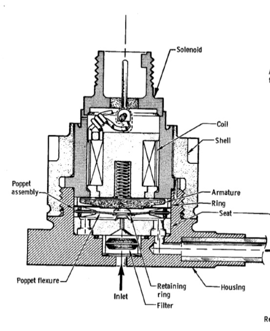
Solenoid valves – The most basic of valves, pretty much make a electromagnet to lift a seal off of an orifice. It is technically a poppet valve, but I classify direct acting solenoids as a different class. These valves are simple, require only power to work, and are readily available in many sizes. But they are relatively large and heavy, especially once your pressure is high or you need a large flow rate. Pretty much the best choice if your orifice is <0.125″ diameter.

Aerospace Solenoid from NASA SP-8094

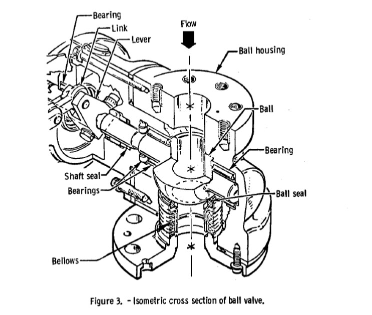
Ball Valves – A sphere with a hole though the middle – align the hole for flow, 90 degree turn to stop flow. These are the workhorses of valves, due to the fact that they are robust and, in the 0.25-3″ orifice, they are the lightest, most compact valve for the size. For most moderate sized rockets (i.e. between 200-50000 lbf), this is probably the main valve for you.

Aerospace ball valve from NASA SP-8094

Poppet Valves- A seal that is lifted off an orifice with a number of actuators, usually pneumatic, hydraulic, or electrical. These are simpler than ball valves, but they have an inherent 90 degree turn at the orifice. They are used in larger valve (6-10″ orifice) and balanced poppet versions are used for high pressure. These valves are also probably the easiest to make from scratch so they are quite popular with small amateur rocket groups.

The current plan for Earendel is a poppet valve that uses a pilot solenoid as an actuator. We will go over the specifics on Friday.

Injector Plan

For Earendel, we are using liquid oxygen and isopropyl alcohol in a pressure fed engine at a relatively low pressure of 180 psi. These conditions make using impinging jet injectors a good first place to start.  Since the flow rate is relatively small and our orifice size is relatively large due to fabrication constraints, this means we will have a small number of elements and they should be unlike jets to promote mixing with the large orifice sizes.  In addition, we will have film cooling protecting the chamber wall so using unlike jets as the main element is fine. After running through some sizing, we end up with unlike impinging doublets as a functional design and the simplest of the impinging jet designs. You can see the injector manifold design below.

Doublet injector manifold from the chamber side with a clear body. LOX in green, Fuel in red.

In addition to a unlike impinging jet, we are also going to experiment with a pintle design. This design will be simpler to manifold and potentially lighter and, thus, cheaper to 3D print. Given the relatively large unknowns in specifically sizing the pintle injector, we expect a few bad performers, either low performance or burning up walls, before we can get something to work.

Pintle injector cross section.

Injector Styles

There are 3 main injector element classification: non impinging jets, impinging jets, and hybrid. The elements are all varied in the method of atomization and mixing. All element types have advantages and disadvantages and the selection of an element type is a function of propellants and desired performance/robustness trade-off. Let’s first go over the different types of injector elements.

Non impinging jets – These are very common and are usually broken into two varieties: the showerhead and the impinging jet. Showerheads were one of the first injectors used in the V-2 and the Aerobee sustainer engine, and they are still used near chamber walls for film cooling. It is basically an array of axial jets and, as such, mixing and atomization are slow for these injectors, but overall uniformity can be good. Showerheads are not often used as main elements because of the low performance but, as I already mentioned, they are used near chamber walls for cooling. I have always wanted to use 3D printing to make a very fine array of showerhead elements to see how that would perform.

Concentric elements are broken into 2 major groups: shear coaxial, which is a tube of propellant A surrounding a rod of propellant B mixing by shear forces, and swirl coaxial, where one or both of the propellants are swirled leading to an injected cone of propellant. These are both very common in gas-liquid injectors, such as the RL-10 and the J2 LOX-H2, but they are hard to make work for a liquid-liquid injection and surprisingly complex as small geometric changes can have signification performance and stability effect.

Impinging Jets –  This is basically direct impingement of jets of propellants. Most of the mixing and atomization occurs at the impingement point of the jets and thus it is important to get the correct momentum ratios to achieve good mixing and atomization. This is done by either varying the pressure drop on the injectors or by adjusting the number of elements. The sizing of the correct momentum ratio is covered in various sources like NASA SP-809 pg 19. Usually these injectors are 1-on-1 (doublet element), 2-on-1 (triplet), 2-on-2 (quad), or 4-on-1 (Pentad).

Like-on-Like impinging is when jets of the same propellant combine and atomize, then mix downstream. This is a good and stable element, but doesn’t have quite as high efficiency as other options. Aligning elements for element to element mixing is key to performance. The elements are also used near chamber walls for reduced wall heating.

Unlike impinging is when jets of dissimilar propellants combine at the impingement points. These elements are an efficient and common choice for liquid to liquid injectors. They do have some stability and injector face heating issues, but are very quick mixing when made properly.

Hybrid Elements- Every other element type gets lumped in here, but it mostly consists of pintle elements and splash-plate injectors, amongst other weirder designs. Pintles are the most common of the other elements and have been used on many designs including the LEM descent engine and SpaceX Merlin engines. The design is a post with radial holes for propellant A at the end of the post and a tube of propellant forms at the base. The  design has some injector face heating and streaking issues, but it also has good performance and chamber wall comparability. It is also uncommon for usually having only 1 injector element per chamber.

Friday we will cover the Earendel rocket injector elements.

Relief Valves

Not a particularly exciting topic, but relief valves are very necessary to most rocket designs. They come in two major flavors: resettable (usually called relief valves) and non-resettable  (usually called burst disks). Both exist to protect your system from inadvertent over pressurization and the related failure: either burst, leak, or component failure.

The first thing you need to do is figure out where they go. A good rule of thumb is that if it can be closed off, it needs to have a relief valve. If you have a small line, <1/2″, and a propellant incapable of increasing in pressure (i.e. not a cryogenic liquid or a monopropellant), you can skip the relief valve in that section. On tanks or other large volume containers, you always need a relief device; if you look at commercial devices like dewars or gas bottles, you will see that they usually have relief valves or burst disks.

Burst Disks – I have always bought commercial burst disks and I would recommend purchasing the disks. They are hard to make as the exact thickness and mounting is important and you have to do batch testing to verify. Use burst disks on things you don’t expect to ever overpressure, like gas pressurant bottles, and be warned they can be VERY loud when they go off.

Relief valve – Lots of designs exist for these, both commercially from places like McMaster or Swagelok and designs from sources like NASA SP-8080. They are good if you need to adjust the relief pressure or if you expect frequent overpressuizations, like on cryogenic vessels. One note is they have some hystorisis, that is to say that if set to 100 psi, they will start hissing at 95 psi, flow fully at 100 psi, then vent down to 90 psi, or something similar.

Remember that safety is the most important thing when you are testing, because if you are not safe, you may not be around to finish the test. And while good procedures and 100% functional devices are good to strive for, relief valves are great to have for when something goes a little wrong with the system.

For reference this is what we are planning to use for relief devices:

– On the Earendel vehicle there will be a burst disk on the pressurant tanks (paintball style) and relief valves on both propellant tanks (McMaster Carr 9137K11).

– On the engine test stand, there will be a burst disk on the Nitrogen Cylinder, a relief valve and a burst disk on the LOX Dewar, relief valves on the propellant tanks, and a relief valve between the isolation valve and the run valve on the LOX run lines.

– On the igniter stand, there is only one relief valve and that is built into the GOX bottle.

3D Printing Rocket

Rockets are perfect for 3D printing technologies, well at least parts of rockets. Bodytubes, maybe not so much, control electronics, also a no, but rocket engines – there’s the ticket. They are relatively small parts with complex internal features and are manufactured in low quantity. Now for the bad news: they get very hot and very cold; they have small features; they are highly stressed. This means, in general, you can only use metal as a material. This limits us to DMLS, Casting and Infused metal.

DMLS is awesome; you send out a part as an stl file and you get a solid metal part back in a couple of weeks. While I have built various 3D printed parts, sadly none of them are mine to show, so instead check out this awesome work at Rocket Moonlighting. For rockets, DMLS materials are usually Inconel or PH 15-5 with other high temperature alloys such as Cobalt Chrome available as well as lightweight aluminum.

Infused metal is somewhat different from DMLS in that a porous version of the model is made, then infused with another alloy. Usually this is 420 SS fill with bronze. It is cheaper and quicker turn around than DMLS but at the expense of detail, only going down to around 40 mil holes vs DMLS 16 mil. Infused metal is also better with overhangs than DMLS. For these reasons, we are using Infused Metal for our igniter and injector, but if we were to make a regen engine we would probably use DMLS.

3D printed (infused metal) igniter as printed. Spark on top; from left to right fuel, pressure, oxidizer.

Casting is just like any other casting method, but it uses 3D printed wax. This technology has been around for decades now and is very common in low volume parts. It is a good technology, but it has a hard time dealing with long passages and thin walls, as well as only being commercially used with easy-to-cast alloys so we are not using it.

Rules of thumb:

If you can machine it, just machine it; it will probably be better, cheaper, and most likely faster.

Infused metal seems to build up more than the stl; allow for a ~4 mil growth.

You will have to tap most threads and, frankly, the surface finish is much improved by taping.

O-rings work fine with any of the 3D printed parts.

On DMLS, limit overhangs to 45 degrees or live with added supports during build.

ASK YOUR VENDOR about what post machining / supports they are adding.

Have a build direction in mind when you design the model; it really helps.

Surface finish isn’t great on DMLS or infused.

Long small holes are much more likely to clog than short small holes.

Make sure you have flats for post machining or wrench tightening.

That’s about it; give it a shot. Nothing says I’m living in the future like 3D printed metal parts arriving in the mail.

3D Printing – General

One of the technologies that will enable broad access to space is 3D printing and rapid prototyping in general. Friday we will cover the use of 3D printing specifically in rockets (mostly DMLS), but today lets just cover the basics of 3D printing.

At heart, 3D printing is manufacturing a component by adding material instead of subtracting material. Instead of removing material by machining away from a brick of material, small pieces of material are fused together to create a solid part. Most 3D printing works layer by layer by adding the material in one layer then stepping up to the next layer and continuing until the end of the file. The most common sorts of 3D printing are fusing filament, sintering, and stereolithography.

Filament Fusing – also know as FDM (Fused Deposition Modeling) – This uses a small filament which is extruded and heated to a liquid, then positioned drip by drip in the right location. Most DIY printers use this and, in general, it is great for prototyping as it is usually cheaper but with with some ridges and layer marks.

Sintering – also know as SLS (Selective Laser Sintering) – This uses a high powered laser to fuse powdered material together. A version of this called DMLS is used for metals. This is great for plastic prototypes and low volume production of all sorts. The main issues are cost for large volumes and getting the powder out of enclosed areas.

Stereolithography – This uses a laser to polymerize a photosensitive liquid. This works very well for surface finish and general build quality, but it is a brittle material so it is only used for fit check and models.

3D printing is a great technology for complex parts in low volumes. Since that is a great definition for rockets in general, we are going to use a fair bit of 3D printing in our designs.

Igniter Software

So now we are sitting around with an igniter and test stand all ready to run it, so we’re good, right? Well not so fast, as some software is necessary. I’m not a software engineer or a CS major by any stretch of the imagination, so I apologize in advance for any painful coding mistakes. It is open source code though, so feel free to tell me what to change or just go ahead and change it on your own if it gets too bad.

Since we are using Arduino for the hardware electronics, we will be using the Arduino  programming environment. Rather than me rehashing how to program in Arduino, check out their website which has some awesome tutorials.

The basic program that we will be using consists of the following parts:

– Initiate variables

– Serial Communication
We use this to get the data from the Arduino on to the serial monitor and to send commands to the Arduio. We don’t have a GUI yet so the commands are:

1- turns on GOX valve
2- turns on IPA valve
3- turns on spark exciter
q- turns off GOX valve
s- turns off IPA valve
e- turns off spark exciter
a- arms the autosequence
s- starst the autosequence
z- aborts the autosequence

This is actually surprisingly easy to use, but we will be adding a GUI over the next month or two.

-Autosequence
You manually set times and what valves change state at those times. The code then iterates and, every 20 ms, updates analog inputs and checks to see if it is at the next time yet.

-Analog Input
Arduino takes 3 data samples separated by 1 ms and averages the data. It then converts the voltage signal to a pressure or temperature.

So that is pretty much it, and you can see a picture of an initial data sample below.

A Data Trace! Temperature is going up after the test because the thermistor is on the outside. All good to go and do some testing.

For those of your that are interested, the code is here as a pdf (originally a *.ino for arduino)  IGNITER_DAQ_LJD_v1 and also in our documentation pages. As with everything else on the site, it is available for use under Creative Commons Attribution-Share Alike.

Igniter Test Stand Electronics

For the igniter test stand, we chose to keep things simple, and, as such, this are our requirements for the electronics:

– 2x Digital Out: Solenoid valve control (12 V)

– 1x Digital Out: Spark exciter (3.3 V)

– 2x Analog In: Pressure transducer  (5 V ratiometric)

– 1x Analog In: Thermistor (10K NTC)

– 1x Serial communication

– Programable autosequence, 10 ms reliability

For this set of requirements, the obvious solution is a microcontroller and it is hard to beat an arduino for accessibility and ease of use. After looking at some spec sheets, we chose the Leonardo due to its native USB communication and the compatibility with Arduino Micro for future flight electronics.

Just like you start a pluming project with a P&ID, you start a electronics project with a circuit diagram. Below is the diagram for the igniter stand as it is currently built in a breadboard configuration.

The schematic gets cluttered in a hurry. It is actually about as complicated to prototype as it was to sketch out.
The pressure transducers and op-amp breadboard. It works well enough in a breadboard, but anything more long term should be soldered.
Arduino, Relay Board, 3.3 V regulator. There is also a 3.3 V channel out of the Arduino, but we need ~0.5 amp so we had to used a stand alone regulator.


Now, everything shown above is sufficient to build a copy of the electronics, but you will need the software which we will post about tomorrow before you can run the stand. Some of the important components are listed below.

Relay Board – SainSmart 4-Channel Relay Module or similar. Note that it is a High Level trigger!

Op Amp – LM358.  And an good site for op amp theory.

Pressure Transducers- TBPDANN150PGUCV This is a non-amplified sensor, which is why the op amp is necessary. It is also very cheap at $20.00, but it really complicates the design. If we were going to do this over, and we will, we would buy some amplified transducers at $60.00 instead.

Thermistor- Finally the thermistor I used and a nice tutorial from adafruit on general thermistor properties.