
In the design of a rocket pumps, one of the biggest drivers is making the pumps as small and thus lightweight and packagable as possible. The main issue is that a small pump inlet has a relatively high velocity and, thus, lower pressure. When the fluid then hits the impeller, the pressure drops further on the back sides of the pump blades. When this pressure drops below the vapor pressure of the pumped liquid, a gas bubble is formed and this process is known as cavitation. This is bad for the pump for two main reasons; the first is that the gas bubble formation can cause high stress and actually destroy the impeller. The second is the gas bubble, with much lower density than a liquid, blocks the flow leading to lower pressure rise and flow rate. To get around this problem, a inducer is commonly added to the inlet of a pump impeller.
An inducer is pretty much a single stage axial pump, usually designed to pressurize the fluid to 10% of the total pump pressure and they are designed to work even with a small amount of cavitation. NASA SP-125 actually has all of the relevant design equations (sample calculation 6-7), so I won’t go over them all again in this post.
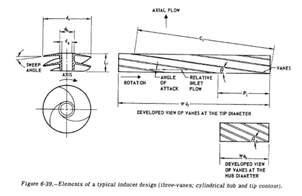
The basics are that you calculate a mean inducer tip speed:
Mean_Tip_Speed = sqrt ( Head_Rise * gravity / Inducer_Head_Coefficient)
with the Inducer_Head_Coefficient being an experimental number between 0.06 and 0.15. From the mean tip speed, you can then calculate the mean diameter and, thus, the inner and outer inducer diameter. Then you calculate the angle of attack at the the front edge using:
Flow_Angle = atan ( Inlet_Axial_Velocity / Inlet_Outer_Tip_Speed)
You then make the inlet vane angle between 1-4 degrees higher than the flow angle. You then take this tip angle and set all of the inlet angles using:
Diameter_A * tan (Angle_Of_Attack_A) = Diameter_B * tan (Angle_Of_Attack_B)
Now, for the outlet, you need to calculate the outlet flow angle using:
Outlet_Flow_Angle = atan ( Outlet_Axial_Velocity / (Mean_Outlet_Peripheral_Speed – Mean_Outlet_Tanjential_Speed))
Then you set the outlet angle equal to the Outlet flow angle + 1 degree to account for real world effects. The final thing is to choose a number of blades, usually 3-5 based on desired solidity, and you are good to go.
As you can see, I glossed over some steps, but with this and SP-125, it is actually easier to design than a impeller so good luck if you give it a go.