Igniter Software

So now we are sitting around with an igniter and test stand all ready to run it, so we’re good, right? Well not so fast, as some software is necessary. I’m not a software engineer or a CS major by any stretch of the imagination, so I apologize in advance for any painful coding mistakes. It is open source code though, so feel free to tell me what to change or just go ahead and change it on your own if it gets too bad.

Since we are using Arduino for the hardware electronics, we will be using the Arduino  programming environment. Rather than me rehashing how to program in Arduino, check out their website which has some awesome tutorials.

The basic program that we will be using consists of the following parts:

– Initiate variables

– Serial Communication
We use this to get the data from the Arduino on to the serial monitor and to send commands to the Arduio. We don’t have a GUI yet so the commands are:

1- turns on GOX valve
2- turns on IPA valve
3- turns on spark exciter
q- turns off GOX valve
s- turns off IPA valve
e- turns off spark exciter
a- arms the autosequence
s- starst the autosequence
z- aborts the autosequence

This is actually surprisingly easy to use, but we will be adding a GUI over the next month or two.

-Autosequence
You manually set times and what valves change state at those times. The code then iterates and, every 20 ms, updates analog inputs and checks to see if it is at the next time yet.

-Analog Input
Arduino takes 3 data samples separated by 1 ms and averages the data. It then converts the voltage signal to a pressure or temperature.

So that is pretty much it, and you can see a picture of an initial data sample below.
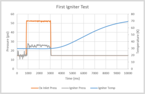
A Data Trace! Temperature is going up after the test because the thermistor is on the outside. All good to go and do some testing.

For those of your that are interested, the code is here as a pdf (originally a *.ino for arduino)  IGNITER_DAQ_LJD_v1 and also in our documentation pages. As with everything else on the site, it is available for use under Creative Commons Attribution-Share Alike.

Igniter Test Stand Electronics

For the igniter test stand, we chose to keep things simple, and, as such, this are our requirements for the electronics:

– 2x Digital Out: Solenoid valve control (12 V)

– 1x Digital Out: Spark exciter (3.3 V)

– 2x Analog In: Pressure transducer  (5 V ratiometric)

– 1x Analog In: Thermistor (10K NTC)

– 1x Serial communication

– Programable autosequence, 10 ms reliability

For this set of requirements, the obvious solution is a microcontroller and it is hard to beat an arduino for accessibility and ease of use. After looking at some spec sheets, we chose the Leonardo due to its native USB communication and the compatibility with Arduino Micro for future flight electronics.

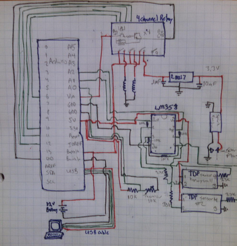
Just like you start a pluming project with a P&ID, you start a electronics project with a circuit diagram. Below is the diagram for the igniter stand as it is currently built in a breadboard configuration.

The schematic gets cluttered in a hurry. It is actually about as complicated to prototype as it was to sketch out.
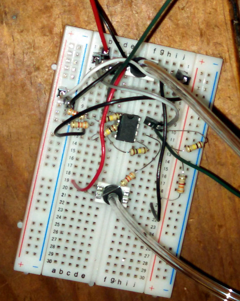
The pressure transducers and op-amp breadboard. It works well enough in a breadboard, but anything more long term should be soldered.
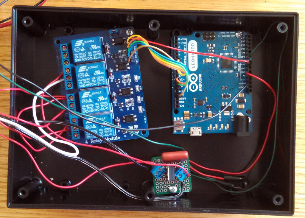
Arduino, Relay Board, 3.3 V regulator. There is also a 3.3 V channel out of the Arduino, but we need ~0.5 amp so we had to used a stand alone regulator.


Now, everything shown above is sufficient to build a copy of the electronics, but you will need the software which we will post about tomorrow before you can run the stand. Some of the important components are listed below.

Relay Board – SainSmart 4-Channel Relay Module or similar. Note that it is a High Level trigger!

Op Amp – LM358.  And an good site for op amp theory.

Pressure Transducers- TBPDANN150PGUCV This is a non-amplified sensor, which is why the op amp is necessary. It is also very cheap at $20.00, but it really complicates the design. If we were going to do this over, and we will, we would buy some amplified transducers at $60.00 instead.

Thermistor- Finally the thermistor I used and a nice tutorial from adafruit on general thermistor properties.