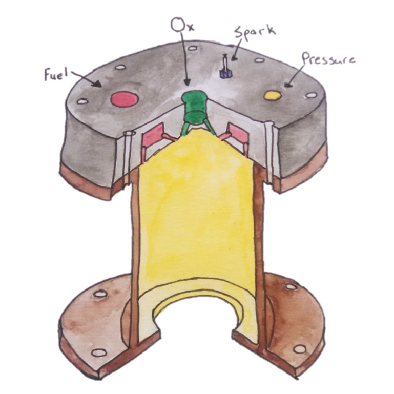
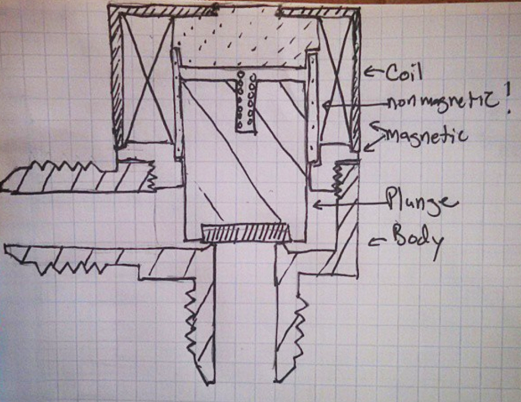
For this post, I’ll go over the basic design of the fuel tank on the Earendel Sounding Rocket.
Step one in any design is the requirements, so here we go:
– 9.6 kg of Isopropyl Alcohol
– 220 psi tank pressure
– 2.5 x Factor of safety
– 3% Ullage (% initial gas) , 3% residual propellant (unburnt at the end)
– For a Sounding Rocket so cylindrical form factor
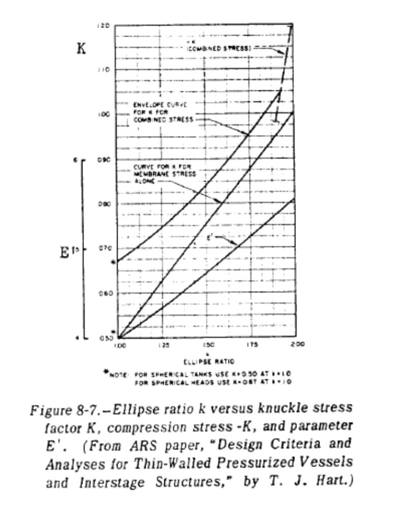
With these requirements, let’s get started with sizing the propellant tank. The first step is the volume of the tank. At a density of 785 kg/m^3, that gives us a propellant volume of 746 in^3 and a tank volume of 791 in^3. If we want a 4-1 cylinder, that gives us a 6.25″ diameter. But to match up with a standard composite tube of 6.02″ ID, we will choose 6.02″ as the ID. Now, for the endcaps, we choose a 60% ellipse as needing roughly the same wall thickness as the sidewall of the cylinder, as you can see in the chart below.
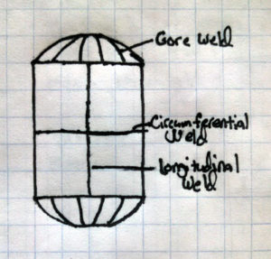
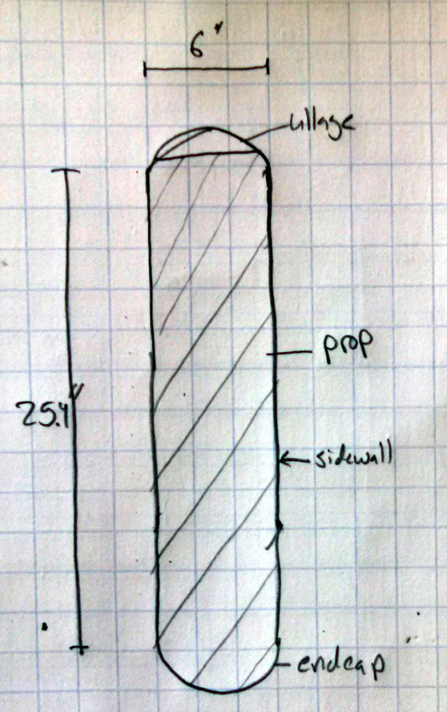
Now this gives us a tank with a 6.02″ ID wall, 25.4″ tall, with 1.8″ tall endcaps. You can see the rough size below and it looks pretty reasonable.
Now a stress analysis for the wall thickness. We will use aluminum 6061-T6 as it is common in 6″ pipes and tubes as well as rods for the endcaps. It has a 42 ksi ultimate strength, and a 35 ksi yield so we can just use the ultimate. The sidewall calculation is fairly easy with:
42 ksi / 2.5 = 220 psi * (6.02″ / 2) / t ==> thickness = 0.0394 that we will just round to 0.040″
For the endcap, using the modifier from SP-125 Fig 8-7 of 0.92 and equation 8-19, we get 0.0344″ for the ellipse thickness. Let’s just round that up to 0.040″ as well to give us margin on any discontinuities.
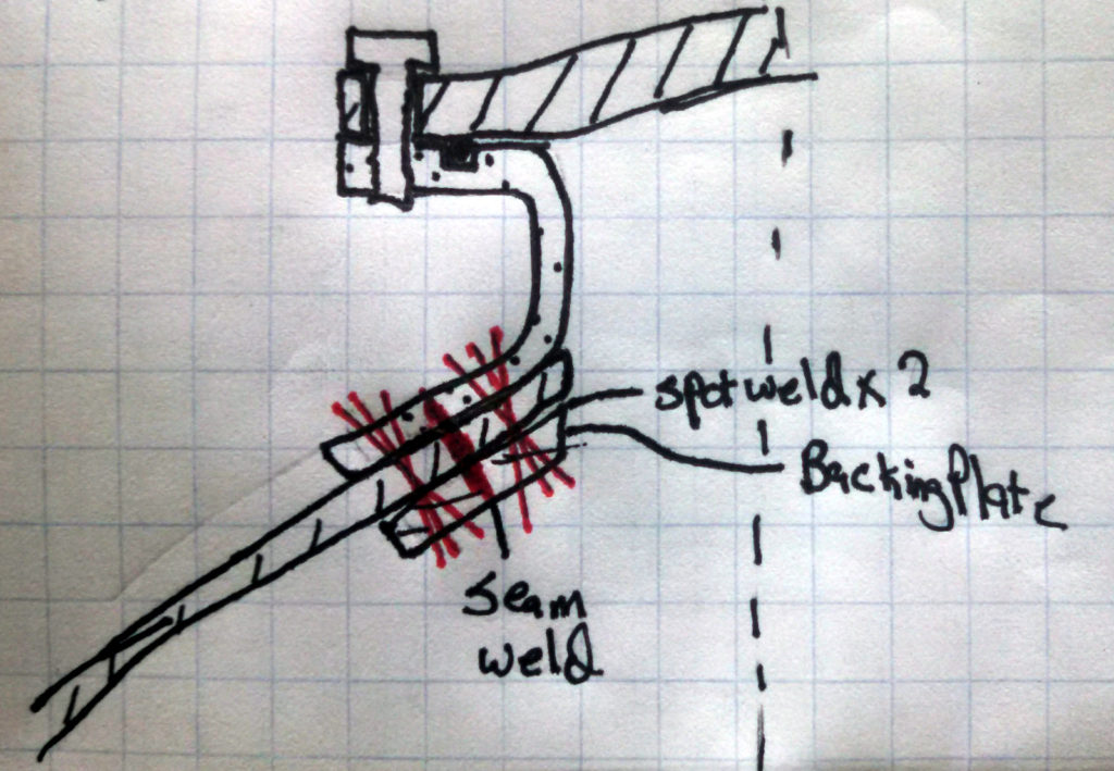
Now for attachments. There should be a bulkhead on both of the endcaps; let’s make it 2.5″ diameter as, from my past experience, that is about as small as is useful for multiple ports. We could also choose to machine ports directly into the tank. This is more expensive and harder to machine and clean, but with the benefit of less seals and a robust mount. So using our flat plate stress analysis, and assuming a bolt diameter of 3.0″, that gives us a thickness of 0.075″. The pressure load is good for 3900 lbf with the 2.5x FoS so that is either 20 #4-40 screws or 14 #6-40 screws or 9 #8-32. So we will just use 10 #8-32 screws.
And the last attachment is the endcaps, which we will use bolts for again. Since the stress area will be around 5.5″ after the bolts go in, that is a load of 13,100 lbf. We want around 20 bolts so that means we have to use 1/4-28 bolts, once again assuming we have Al-6061 bolts.
One word about aluminum bolts: The most common bolt is 7075-T73 or 2024-T4 which are OK for cryogenic service and are stronger than 6061. So we are being conservative with the bolt strength. Please double check your vendor though because some bolts are 3000 or 1000 series alloys which are very weak by comparison.
Now for the seals. There are two of them: the bulkhead and the endcap. We will use viton o-rings as they are cheap, available, and work very well. We will also use 1 O-ring per seal; there is no redundant seal, which is fine for our application, but sometimes frowned upon in high risk fault intolerant systems. I highly recommend the Parker O-ring handbook. In this case, I used it and will be using a face seal gland with a #38 O-ring on the bulkhead and a #160 O-ring on the endcap.
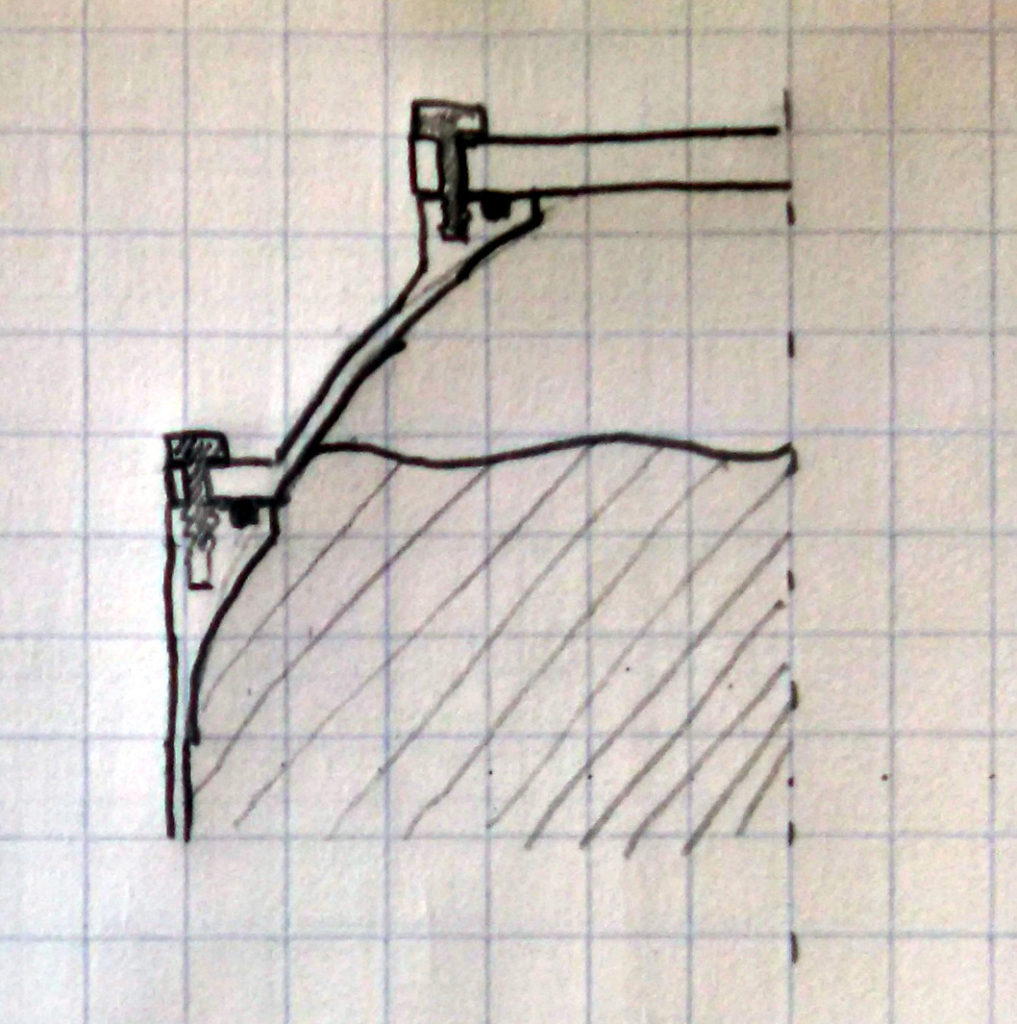
This is the end of the initial design. At this point, you will want to model the tank, check its weight, run a stress analysis, and see how it lines up and mounts with other structures in your system. Good luck, and be prepared for the inevitable redesign!

